Serial I/O Conversion and Relocation
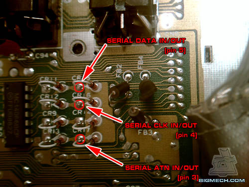
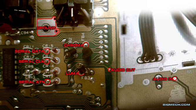
Recognize this image? You should. It's the same one I used for the S-video and audio out mods. This is where all of the cool solder points hang out. The Serial I/O will need to be relocated because I plan to use that space for the DIN Sync input.
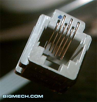
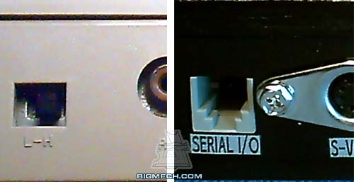
I added a Serial I/O port to my mini C64 using an RJ11 jack since space was a major issue with that project, and the connector needed to house six conductors.
RJ11 connectors are able to hold up to six conductors, but typically only have four. So, it is usually necessary to add the last two.
I decided to add the same jack to my 64C so they would both be compatible with my 1541emu rig. It also gives me something to do with that square opening on the back of my 64C enclosure (originally used to select the RF Ch.3-Ch.4).
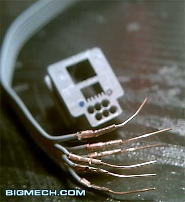
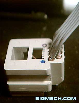
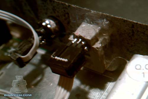
Again, I added pins to the back and made a connector rather than directly soldering the wires to the jack.
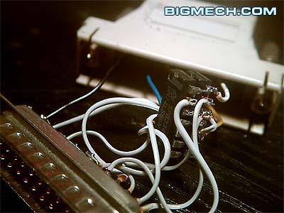
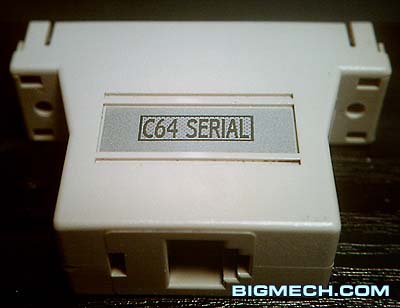
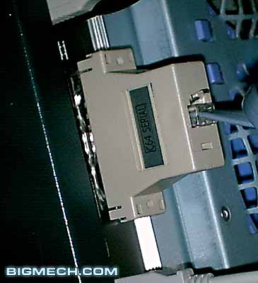
The serial to 1541emu adapter requires additional circuitry.
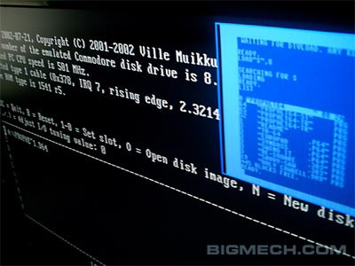
I won't go into detail about 1541emu since you may choose another method, or you may not wish to use any type of floppy device.
If ever I need to hook up an actual C64 floppy drive, I still have the serial DIN connector. Making a RJ11 to DIN adapter would be simple. I doubt Iíll ever need one though. This works flawlessly!
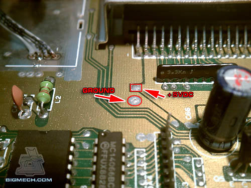
Since the adapter is external, I needed to tap +5VDC to power the ICs. While information on creating a 1541emu cable is available online, I thought it would be worth noting where to find +5VDC on the main board.
Here is that special part of the board with all of the solder points labeled. NEXT» |
