The following is a technique I used while assembling a circuit to be installed where space was very limited.
Make sure your circuit design is finalized. Changes will be extremely difficult once the circuit is complete.
 | |
I based the circuit around the largest component.
|
 | |
I bent the pins to prepare the IC. This technique involves a lot of thinking ahead.
|
 | |
I first joined the common pins of the IC knowing that this area will not be accessible for much longer.
|
 | |
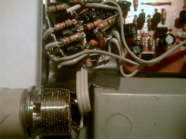
Every component needed to be prepared before installation.
|
 | |
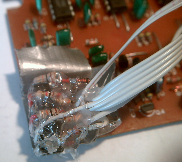
Occasionally, I had to insulate component leads.
|
 | |
Looking at the schematic, one would expect this circuit to be much larger than a quarter.
|
UPDATE:
Shortly after this was featured on Hack-A-Day, I began receiving email asking about this circuit.
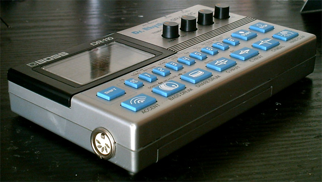
This is a revised version of my original DR-110 sync mod. The original design bypassed the internal clock with divided down sync 24 clock signals which were provided by an external master clock device feeding into the 110 via a standard Roland Din Sync (five pin din) port. And, they said it couldn't be done. The schematic above is a revision which also utilizes the incoming Din Sync Run/Stop signal to control the Start and Stop functions on the DR-110. If ever I revisit this project, I'll be sure to use SMD components for an even smaller circuit.
I intentionally made the schematic virtually indecipherable. Why? Back in 1997, when I first developed the mod, I posted the schematic with a full description of how it worked along with the necessary steps one would take to interface this circuit with their 110. My goal was to bring the DR-110 into the studio by enabling it to sync with other gear, as I have done with other devices. After receiving email from musicians asking me to perform the mod on their DR-110s, I eventually decided to do so via snail mail. This was to supplement my funds, or lack thereof, while I was in college. Apparently, the pocket change I earned was enough to gain the attention of a few companies specializing in modding (usually butchering) analog synths. These chop-shops used my design to offer DR-110 sync modding service with a ridiculous premium. Of course, they based their work off of my original design. Therefore, 110's modded by them lack the ability to utilize the run/stop feature.
So, I'm keeping the revised version of the mod under my hat for awhile. ;) To this day, I still receive email requesting that I perform the mod. Although, I have officially stopped doing that, I did bust a few out for a handful of 110 owners a few years ago. If you had me mod yours after 2004, you have the new revised circuit, shown above, in your 110 right now! So, there are a few "Second Generation" DR-110's floating around out there.
And, if anyone manages to figure out how it works by analyzing the images on this page, then, I guess they will have earned the knowledge.
-Alpha
UPDATE UPDATE!:
I've had a change of heart. There is no sense in keeping modders from the information they have asked for. If someone wants to thief my work again, have at it.
Anyone with experience in electronics may find this circuit odd. And, it is. At first glance, it doesn't look like it would work. Especially the Start/Stop portion of it. I assure you that it does. I didn't want to involve a microcontroller, since that would be overkill (even though everybody does so now), and I wanted to be sure not to introduce any latency by passing the original incoming din sync Clock and Start-Stop signals to the 110. I had to use some trickery to pull it off.
Enjoy.
 I recommend adding an opto-isolator if you have other gear sharing an unbuffered Din Sync line (EG. if you're using a passive splitter). This will assure that the above 110 Sync Circuit doesn't interfere with the incoming (shared) sync signal. I've experienced a little of this. Isolation will easily remedy any issues.
Also, you SHOULD be able to get away with swapping out the 2N2222 transistors with the more common 2N3904. The 2N2222 can handle more amps, but is otherwise identical in design. The same can be said for the 2N2097 transistor verses a 2N3906. All are very common components, and you shouldn't have trouble finding any of them. Depending on what you have on hand, you may find this bit of info handy.
|
|
 Featured on Hack-A-Day!