Steel Battalion
Controller Mod
By: AlphA
| RUMBLE |
Enhanced Control Circuit
UPDATE! |
I revamped the control circuit to give it more oomph. The effects of the original design were too faint.
The rumble effect, in general, was designed to create the shaking effect without sacrificing control, unlike force feedback. So, it’s safe to take it up a notch. In fact, it can actually enhance your abilities by creating an additional sense of awareness. When you take a hit, you know it!
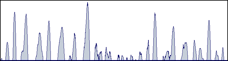
This graph demonstrates typical output from the original control circuit. It is basically an amplified version of the LED illumination. Notice it varies in timing and amplification. As this is great for lighting effects, it is not the most efficient signal for driving a motor.
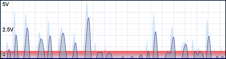
In this graph, we see how the original control circuit’s output influences the motors. Compare the two charts. Notice how the peaks have been rounded off, short signals have virtually no influence on the motors, and the motors never reach there full 5V potential. This is due to the sluggish nature of motors. It is not possible to switch between full stop and full speed instantly- Especially, when those motors need to gather enough momentum to swing unbalanced weight around. Voltage below the minimal requirement for spinning the motors is represented by the red area. Clearly, much is lost.
The new control circuit overcomes this issue by implementing a monostable circuit. One of the functions of this addition will cause the output that drives the transistor to be at max any time output from the LED is greater than ground. This is illustrated by the chart below.
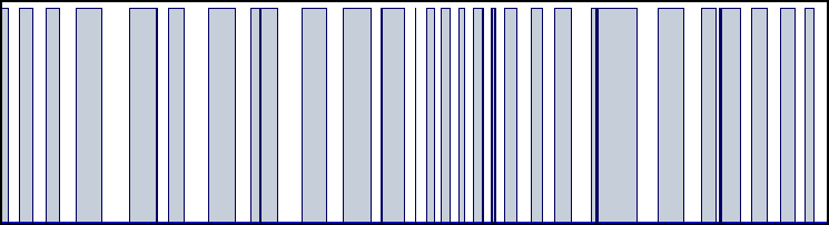
Notice the output swings from max to off, like a switch. This is great for driving motors. Even the dullest signals will cause the output to be at max.
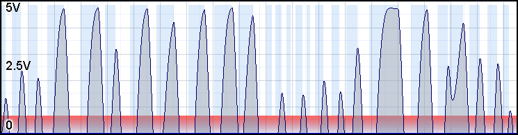
Here we see how this new circuit will influence the motors. Notice, the voltage often reaches the 5v area.
In addition, the monostable circuit has another great function. The minimal length of the output pulses can have a set value. EG: If it takes the motors .5 seconds to switch from full stop to full speed, you can set the minimal pulse length to .5 seconds. Therefore, the fastest dullest signal will put the motors near full power every time.
| NOTE: Minimal pulse length can be set by the values of the resistor(2.2k) and capacitor(100uF) as follows. Time = Resistor * Capacitor |
Here is the new schematic:
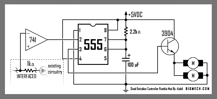
The 741 now acts as a buffer and inverter. The 555 converts anything above
0 at it's input to max output. This drives the transistor which allows power
to pass to the motors.
The 2.2k resistor can be swapped with a potentiometer for manual adjustment of the minimal pulse length. Another potentiometer can be interfaced between pin 3 of the 555 and the base of the transistor to control the amount of rumble.
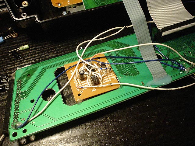
This time, I decided to mount the mod components on to a project PC board.